
Layout of a building or a structure shows the plan of its foundation on the ground surface according to its drawings, so that excavation can be carried out exactly where required and position and orientation of the building is exactly specified. It is set out according to foundation plan drawings and specifications provided by the engineer or an architect.In order to understand layout or setting out of a building we must understand some of the technical terms related to this job which are described below.
BASELINE
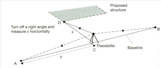
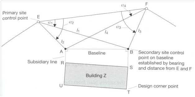
A baseline is a straight reference line with respect to which corners of the building are located on the ground. It may be outer boundary of a road or curb or boundary of the area or simply a line joining any two points.
HORIZONTAL CONTROLS
Horizontal controls are the points that have known co-ordinates with respect to a specific point. These points are then used to locate other points such as corners of a layout using various techniques. There should be plenty of control points so that each point of foundation plan can be located precisely on the ground.
VERTICAL CONTROLS
 In order that design points on the works can be positioned at their correct levels, vertical control points of known elevation relative to some specified vertical datum are established. In practice, 20mm diameter steel bolts and 100mmlong, with known reduce levels driven into existing steps, ledges, footpaths etc. may serve as vertical controls.
BATTERBOARDS AND OFFSET PEGS
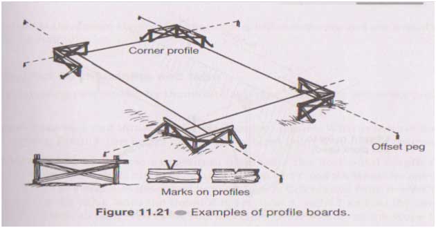
Once points specifying the layout are located on ground pegs are driven in the ground at that spot. Once excavations for foundations begin, the corner pegs will be lost. To avoid these extra pegs called offset pegs are used. Batter boards are normally erected near each offset peg and are used to relocate the points after the excavation has been done.
LAYING OUT A RECTANGULAR BUILDING SITE
Starting from a baseline (line AB in Figure 4-1) that is parallel to construction, establish the maximum outer borders (AB, CD, AC, BD) of the building area.
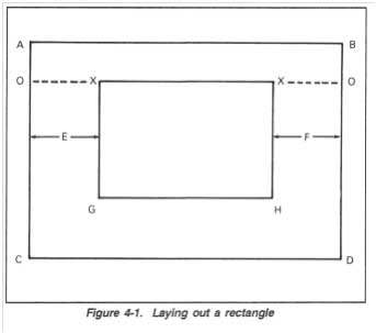 Suppose we know the co-ordinates(x,y) of the points X with respect to point A then we can locate it by measuring their x distance along line AB and y distance along line AC and BD respectively to locate them. These two points can be joined to make line XX. To locate point G and H, straight line are set out using 3-4-5 triangle rule and distance XG and XH which is known is marked on those lines. After the four corners (X, X, G. and H) have been located, drive stakes at each corner. Dimensions are determined accurately during each step.
LAYING OUT AN IRREGULAR BUILDING SITE
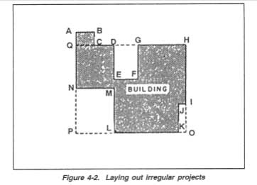 Where the outline of the building is other than a rectangle, the procedure in establishing each point is the same as defined for laying out a simple rectangle. However, more points have to be positioned, and the final proving of the work is more likely to disclose a small error. When the building is an irregular shape, it is sensible to first lay out a large rectangle which will includes the entire building or the greater part of it. This is shown in Figure 4-2 as HOPQ When this is established, the remaining portion of the layout will consist of small rectangles, each of which can be laid out and shown separately. These rectangles are shown as LMNP ABCQ, DEFG, and IJKO in Figure
EXTENDING LINES
Since the corner pegs of the building are to be removed during excavation these points are transferred outside that periphery by extending lines and driving pegs in the ground. The following procedure applies to a simple layout as shown in Figure 4-4, page 4-4, and must be amended to apply to different or
more complex layout problems:
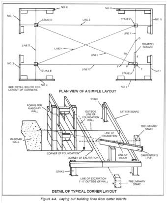
Step 1: After locating and dipping stakes A and B. erect batter boards
1, 2, 3, and 4. Extend a chalk line (X) from batter board 1 to batter
board 3, over stakes A and B.
Step 2: After locating and dipping stake C, erect batter boards 5 and
- Extend chalk line Y from batter board 2 over stakes A and C to
batter board 6.
Step 3: After locating and dipping stake D, erect batter boards 7 and
- Extend chalk line Z from batter board 5 to batter board 7, over
stakes C and D.
Step 4: Extend line O from batter board 8 to batter board 4, over stakes D and B.
Where foundation walls are wide at the bottom and extend beyond the outside dimensions of the building, the excavation must be larger than the laid-out size. To lay out dimensions of this excavation, measure out as far as required from the building line on each batter board and stretch lines between these points, outside the first layout.